Monday, December 20, 2010

Back Tracking 01

Then


Back


Now


Bad blogging habit.

i have a terrible habit with blogging, where by i save things to drafts and never post them, and forget about them.

FINAL THOUGHTS :

The most valuable lesson I learned from Art&Tech is that technology is a temperamental media. there is a significant amount of planning that needs to be done as well as knowing the nature of the particular type of technology you are dealing with and its idiosyncrasies. Chances are I should have learned this lesson when 2 years ago my lap top just stopped working, midterms week, and then my flash drive went missing. Never the less, in this class specifically, it was challenging to work projects into technology, not the other way around. If you don't think technologically, you work will suffer. If you are over ambitious - your work will suffer. There is, I think, an expectation, at least for me, that naively thinks that "oh, that will work" or "how hard can that be?". The truth is, that won't work, its harder than you think, and anything that can go wrong will go wrong and if you think you've fixed it, please, think again.

Group Work
It is really difficult to work with technology you aren't sure if it will work, but add other people's temperaments, schedules, lives with an already temperamental medium, and you've got stressed out right there. That's really all I have to say on that.

Sound:
Reflection : Circuit bending is a low art, its low tech, low fi, and mildly si-fi. It should stay that way. Why? This goes into an "unmonumental" type argument. I think, personally, that there should be a refinement to academic work either conceptually, or physically. It is really, almost unachievable with a method like Circuit bending, if re contexualizing is the concept, we were already handed that. Art historically speaking, John Cage would have been amused, but he already took the avante-sound to an installation style and performance style (this is mostly for my own thoughts on the piece my group did an a flaws i found within my way of approaching it, not the assignment - to clarify. this is more or less, a self evaluation of approach.)

Social Change :
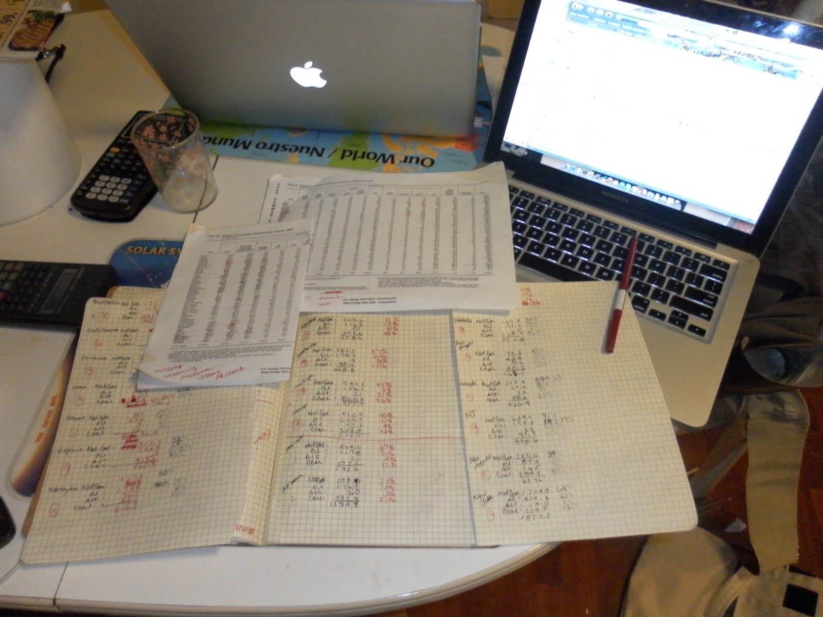
I attempted to keep it clean simple and basic for my own means and sanity. That didn't pan out too well. While i do think there was an awareness element, I have that, and what sort of feeling. Visually im pleased with the map. and physically, when it did work i was pleased with that. however personally, social change is a medium for action, not technology. as far as im concerned, technology is overwhelming the social change movement, and the information has those who are concerned stretched emotionally thin, and overwhelmed. I do however firmly believe that knowledge is the first step. (again, self evaluation of approach upon further reflection)

PROJECT 1

PROJECT 2

Tuesday, November 30, 2010

_distraction_


LINK HERE


check it out! they have an interesting article on art and tech (preview below) also, the screen shot is my feature.


art 21 has a blog! which you can add to your google feed (news, art 21, gmail, horoscope. igoogle : complete)

Monday, November 29, 2010

Project 2 - Improvements


To improve :


Lines on map
More labeling ie: state names, state boarders, graph info


consider :

- bar-code app scanning.
- maybe color (?)
- think of a location (render in google sketch?)
- website (and/or link to further info)


Also include

a Power Point of a mock grant proposal.

in front of committee :
asking for money w/ show and tell some performance

Friday, November 12, 2010

PROJECT_2 : DEATH (p2)

ALSO

After talking with Arthur, there is no way to cut the text with the CNC, it is not like the laser cutter. the scale and font art just won't work, the scale is the main issue. WHAT A BUMMER. so on ward to plan B - stenciling. considered using the laser cutter to cut the text, but it really seems like more hassle than its worth to just make it by hand at this point.


we also talked a little bit about why he works digital, i really couldn't understand why a 3-d artist would work soo heavily with computers and digi.fab. so basically from what i took from his reply to "so why how did you start working in digi.fab?" was that it started as a rendering tool, and then an output tool. it makes much more sense from that approach, insofar as its a tool used not applied. which is where i think, many of our projects are really lacking. this is to say the way the project is planned, and plotted out.

PROJECT_2 : DEATH (p1)

so anything that can go wrong will go wrong.


SO. through the graces of arthur hash, we are working on getting our file cut asap.
we were supposed to meet this morning however, access to the wood shop proved to be lacking on my end, and knocking was no help. SO. meeting roughly 2 hours late than planned, only to find out that the rhino file, even in what i thought was pared down terms was not pared down enough. (great.) However he did help us out a bit with a illustrator image (seen above) so a BIG thank you to him for that to help cut down the ediding a bit.

one thing i love are YOUTUBE video tutorials. everything should have a video tutorial. the ability to pause and rewind is AWESOME.


in other techy news: photo resistors are a no go. it looks like we are using buttons.


its make it work time.

Thursday, November 11, 2010

PROJECT_2 : rhino part 2


so what you see here is a rhino attacking N.J.


(back to) PROJECT_2 : rhino

this is how i feel right now :


PROJECT_3 : few things before putting it on the back burner

SO. despite my best efforts to not use group work... i am working in a group, via my own asking. After the presentations last week, i really responded to the work that Celine is thinking about, I saw some over laps in translucent materials as well as interest in text, and relation ship to the viewer.

Josh (i believe) approached Celine to work as a partner, and we all met roughly an hour later to discuss things. after looking at Josh's project plan he and I had a similar map out for an an environment and use of a sort of maze (for lack of a better word) design.

so we have some pretty solid over laps in over all construction but are really open for concept. however its crunch time for project two, so we exchanged contact info, and will be placing this project on the back burner.

this is mildly exciting.

(back to) PROJECT_2 : getting closer and closer to finishing!


(Below) Ben working on the LEDs for our graph portion of the project. (Above) is the data that chart is based on.


Sunday, November 7, 2010

lo-fi 3D Lego Digitize

while browsing around the internet i found this article of interest

http://www.rchoetzlein.com/project/digitizer/


(these images are lifted from the page, but it gives you an idea of whats linked above)


ardunio_typewriter

A new way to interact with fiction from Jonathan M. Guberman on Vimeo.


"Automatypewriter is a project by Jonathan Guberman of Site 3 coLaboratory hackerspace in Toronto that features an Arduino controlled typewriter that can type on its own as well as detect what is being typed on it. Here’s a demo of the Automatypewriter playing the classic text aventure game Zork."

Friday, November 5, 2010

PROJECT_2 : Even more Digiprogress.


/*
* Show messages on an 8x8 led matrix,
* scrolling from right to left.
*
* Uses FrequencyTimer2 library to
* constantly run an interrupt routine
* at a specified frequency. This
* refreshes the display without the
* main loop having to do anything.
*
*/

#include

#define SPACE { \
{0, 0, 0, 0, 0, 0, 0, 0}, \
{0, 0, 0, 0, 0, 0, 0, 0}, \
{0, 0, 0, 0, 0, 0, 0, 0}, \
{0, 0, 0, 0, 0, 0, 0, 0}, \
{0, 0, 0, 0, 0, 0, 0, 0}, \
{0, 0, 0, 0, 0, 0, 0, 0}, \
{0, 0, 0, 0, 0, 0, 0, 0}, \
{0, 0, 0, 0, 0, 0, 0, 0} \
}

#define H { \
{0, 1, 0, 0, 0, 0, 1, 0}, \
{0, 1, 0, 0, 0, 0, 1, 0}, \
{0, 1, 0, 0, 0, 0, 1, 0}, \
{0, 1, 1, 1, 1, 1, 1, 0}, \
{0, 1, 0, 0, 0, 0, 1, 0}, \
{0, 1, 0, 0, 0, 0, 1, 0}, \
{0, 1, 0, 0, 0, 0, 1, 0}, \
{0, 1, 0, 0, 0, 0, 1, 0} \
}

#define E { \
{0, 1, 1, 1, 1, 1, 1, 0}, \
{0, 1, 0, 0, 0, 0, 0, 0}, \
{0, 1, 0, 0, 0, 0, 0, 0}, \
{0, 1, 1, 1, 1, 1, 1, 0}, \
{0, 1, 0, 0, 0, 0, 0, 0}, \
{0, 1, 0, 0, 0, 0, 0, 0}, \
{0, 1, 0, 0, 0, 0, 0, 0}, \
{0, 1, 1, 1, 1, 1, 1, 0} \
}

#define L { \
{0, 1, 0, 0, 0, 0, 0, 0}, \
{0, 1, 0, 0, 0, 0, 0, 0}, \
{0, 1, 0, 0, 0, 0, 0, 0}, \
{0, 1, 0, 0, 0, 0, 0, 0}, \
{0, 1, 0, 0, 0, 0, 0, 0}, \
{0, 1, 0, 0, 0, 0, 0, 0}, \
{0, 1, 0, 0, 0, 0, 0, 0}, \
{0, 1, 1, 1, 1, 1, 1, 0} \
}

#define O { \
{0, 0, 0, 1, 1, 0, 0, 0}, \
{0, 0, 1, 0, 0, 1, 0, 0}, \
{0, 1, 0, 0, 0, 0, 1, 0}, \
{0, 1, 0, 0, 0, 0, 1, 0}, \
{0, 1, 0, 0, 0, 0, 1, 0}, \
{0, 1, 0, 0, 0, 0, 1, 0}, \
{0, 0, 1, 0, 0, 1, 0, 0}, \
{0, 0, 0, 1, 1, 0, 0, 0} \
}

byte col = 0;
byte leds[8][8];

// pin[xx] on led matrix connected to nn on Arduino (-1 is dummy to make array start at pos 1)
int pins[17]= {-1, 5, 4, 3, 2, 14, 15, 16, 17, 13, 12, 11, 10, 9, 8, 7, 6};

// col[xx] of leds = pin yy on led matrix
int cols[8] = {pins[13], pins[3], pins[4], pins[10], pins[06], pins[11], pins[15], pins[16]};

// row[xx] of leds = pin yy on led matrix
int rows[8] = {pins[9], pins[14], pins[8], pins[12], pins[1], pins[7], pins[2], pins[5]};

const int numPatterns = 6;
byte patterns[numPatterns][8][8] = {
H,E,L,L,O,SPACE
};

int pattern = 0;

void setup() {
// sets the pins as output
for (int i = 1; i <= 16; i++) {
pinMode(pins[i], OUTPUT);
}

// set up cols and rows
for (int i = 1; i <= 8; i++) {
digitalWrite(cols[i - 1], LOW);
}

for (int i = 1; i <= 8; i++) {
digitalWrite(rows[i - 1], LOW);
}

clearLeds();

// Turn off toggling of pin 11
FrequencyTimer2::disable();
// Set refresh rate (interrupt timeout period)
FrequencyTimer2::setPeriod(2000);
// Set interrupt routine to be called
FrequencyTimer2::setOnOverflow(display);

setPattern(pattern);
}

void loop() {
pattern = ++pattern % numPatterns;
slidePattern(pattern, 60);
}

void clearLeds() {
// Clear display array
for (int i = 0; i < 8; i++) {
for (int j = 0; j < 8; j++) {
leds[i][j] = 0;
}
}
}

void setPattern(int pattern) {
for (int i = 0; i < 8; i++) {
for (int j = 0; j < 8; j++) {
leds[i][j] = patterns[pattern][i][j];
}
}
}

void slidePattern(int pattern, int del) {
for (int l = 0; l < 8; l++) {
for (int i = 0; i < 7; i++) {
for (int j = 0; j < 8; j++) {
leds[j][i] = leds[j][i+1];
}
}
for (int j = 0; j < 8; j++) {
leds[j][7] = patterns[pattern][j][0 + l];
}
delay(del);
}
}

// Interrupt routine
void display() {
digitalWrite(cols[col], LOW); // Turn whole previous column off
col++;
if (col == 8) {
col = 0;
}
for (int row = 0; row < 8; row++) {
if (leds[col][7 - row] == 1) {
digitalWrite(rows[row], LOW); // Turn on this led
}
else {
digitalWrite(rows[row], HIGH); // Turn off this led
}
}
digitalWrite(cols[col], HIGH); // Turn whole column on at once (for equal lighting times)
}

PROJECT_2 : Digiprogress con't


MORE RHINO PROGRESS...


so far so good with rhino! i never thought i would say this, but i am mildly enjoying the program ... (granted, its probably because ben and liz is here whenever something gets terribly confusing)

so it is to my understanding that each layer of cutting has to be saved in an individual file to be routed out. so from the original rhino sketch i broke it down into three individual files.


SOME OTHER CONSIDERATIONS.

-we are considering painting the entire board a high gloss black, which, i am fond of initial but upon further reflection am not sure how to make the text clear to read... however...nother contrasting color should be an easy enough fix.... we shall see...

-LED colors used for the light scale are red (oil) orange (natural gas) yellow (coal) green (alternative) while the color scale may boarder on cliche, the idea is to make as clear and cohesive as possible, using colors such as blues and greens or purples and pinks do not have the same color association as the yellow to red spectrum (similar to the color code system used for terror alerts). So, rather than viewing it as cliche, its an established color palette for the issues we are addressing.

DIGI-INFO
Ben has been plugging away at trying to figure out get the most from the dweenies, in considering multiplexer/demulitlexers. this is order to increase the amount of info being received and processed by the micro-controllers : delightful. because this is an an analogue input to the boards, we need to get analogue multiplexers to disperse this info. to the LEDs. so there are 48 photo resistors and 40 LEDS that should theoretically work in a grid like pattern to send and receive the codes so that way the the LEDS correspond to the assigned photo resistor.

Thursday, November 4, 2010

PROJECT_2 : Digital Progress!


Ben and I worked on the original file that he and Liz created. We resides, scaling the image by ten, then again by ten. Centered it and added text boxes for the information. the circles are at 1/4 of an inch diameter and we have LEDs to match. there 4 rows of 10, each LED will indicate 10% of energy usage per state.

PROJECT_2 some other ways of visualizing data


http://flowingdata.com/2008/12/19/5-best-data-visualization-projects-of-the-year/

while there are some more visually simulating ways to display data, the clarity comes at a cost.
i personally prefer something that is more clear, simple, and minimal, rather than something more elaborate and harder to comprehend.


Tuesday, October 26, 2010

PROJECT_2 some other info

Ben found a great site with some fun information about solar power projects.


Monday, October 25, 2010

PROJECT_2 some revsions, some updates


after discussing out idea, we have decided to scale it down to just the united states. this is because it is a smaller scale of place, and the viewer can identify more closely with their position in the world, if one relates it to a space they can form a close attachment to.

so we will be using a relief of the united states, as cut by a CNC router, via an STL file of the rendering.


EXCITING THINGS!

Monday, October 18, 2010

PROJECT_2

GROUP : Mary, Liz, Ben

(liz and me with ben's sketch)

Topic : peak oil


WHY : according to geologists, we have reached the peak of the earths oil. this does not mean that we are running out of oil per-say but what it does mean is that the cost to extract oil will be more than the return on the investment. this issue is very controversial, even for environmentalists. we plan on making in interactive map where by the viewer can see the use of a reserve... project cost per year... shedding light on an issue is the first step to creating social change. by creating an interactive piece it cause the viewer handle the information physically, it becomes concrete.


Socail Scupture


Social Sculpture

i dont know why i cant think of tech art without thinking of tvs. maybe its because i love gary hill. maybe its because its as hi-tech as i get. i read that you can make little TV using dweenies, so that's what i plan to do. with some help of an engineer, i would like to make them interactive... and set up a webiste that is in real time. (but that might be slightly ambitious... for me)

SKETCH
INSPIRATION
(gary hill)


Sunday, October 17, 2010

site of interest

Electronic Arts Intermix


http://www.eai.org/title.htm?id=3903

Arduino_Photocell

so, moving forward with dweenie, on to photocells. Lets give it a go... and we are ... not quite succesful. hm. okay so leme break down what im seeing here


i have the orange wire attached to the 11 digital in, which is the same column as the resistor (1). the other end of the resistor (1) goes into the positive side of the LED. The negative side of the LED goes the same column as the green wire, which attaches to the other resistor (2) and the ground through the black wire. the other side of the resistor (2) goes to the negative side of photocell, and the blue wire which goes to the 0 analog in. the positive side of the photocell is in the same column as the red wire which goes to power (5v). BAH what has gone wrong?!


i used the code following the diagram.


but this happened...


:(

Arduino_Knock

so. me and dweenie were getting along near famously until the knock sensor. i forgot something, whereby when i knocked, nothing happened.... (uh-oh)


i followed the little diagram, but using the breadboard
so, that wasnt making full sense to me, so i read the schematics...


and ended up here... and kept going...


used the knock code... but nothing happened?


hmmmm.